

- HomeProducts
-

Why Automotive Electronics Need Selective Soldering Solutions
Views: 0 Author: Site Editor Publish Time: 2026-08-31 Origin: Site


The shift to electric vehicles (EVs) and advanced driver-assistance systems (ADAS) pushes vehicle architectures to their absolute limits. Modern control units pack highly dense, mixed-technology components that demand zero-defect manufacturing. Traditional soldering methods fail when processing boards with extreme thermal mass, heavy copper layers, and tightly packed, heat-sensitive surface-mount devices (SMDs). Applying full-board heat causes thermal damage, while manual masking and rework drive up labor costs and defect rates. Selective soldering bridges the gap between high-throughput production and pinpoint precision. As a programmable evolution of wave soldering, it applies flux and solder only where needed. This targeted approach allows manufacturers to meet stringent automotive reliability standards without sacrificing scalability. Current industry trends show automotive electronics soldering rapidly adopting selective systems as the baseline standard, future-proofing assembly lines against increasingly complex, miniaturized board designs.
Key Takeaways
Targeted Thermal Control: Selective soldering isolates heat application to specific through-hole joints, eliminating thermal shock to adjacent sensitive components and protecting tricky electronic parts.
Automated Repeatability: Programmable fluxing and soldering cycles guarantee the consistency required to create reliable through-hole joints that meet IPC-A-610 Class 3 and IATF 16949 automotive standards.
Cost-to-Yield Optimization: While initial capital expenditure is higher than traditional wave systems, the elimination of masking, reduced rework, and minimized defect rates drive a verifiable long-term ROI.
Mitigating Implementation Risks: Success depends heavily on proper equipment sizing, nitrogen management, and partnering with an experienced electronics manufacturing supplier for integration and training.
The Unique Demands of Automotive PCB Assembly
Thermal Mass and Heavy Copper Boards
EV power distribution modules and inverter boards frequently utilize 3-ounce to 6-ounce copper layers to handle massive current loads. These thick copper planes act as aggressive heat sinks. When a standard soldering iron or a fast-moving wave hits these pins, the copper instantly wicks the thermal energy away from the joint. The solder freezes before it can flow up the barrel, leaving you with a cold joint or less than 50% hole fill. Overcoming this physics problem requires sustained, localized thermal energy that traditional full-board methods simply cannot provide without burning the FR4 substrate.
Vibration Resistance and Harsh Environments
Engine control units (ECUs) mounted directly to the block face relentless mechanical vibration and thermal cycling from -40°C to +150°C. A solder joint in this environment is a structural anchor, not just an electrical connection. If the through-hole barrel lacks 100% fill or exhibits a poor wetting angle, micro-cracks will propagate through the joint under stress. Within a few thousand miles, the connection shears, and the vehicle loses power. Automotive standards demand perfect capillary action and void-free joints to survive these harsh under-hood conditions.
The Mixed-Technology Challenge
Modern automotive PCB assembly rarely involves uniform component types. You will often find microscopic 0201 SMDs placed mere millimeters away from massive, high-power through-hole relays or electrolytic capacitors. This mixed-technology reality forces a highly localized soldering approach. Applying blanket heat to secure a heavy connector risks reflowing or thermally destroying the adjacent micro-components. Manufacturers need a process that can deliver intense heat to a specific 3mm area while keeping the surrounding board at a safe baseline temperature.
High-Density Component Layouts
Automotive designers constantly push for miniaturization to save weight and space. They pack more functionality into smaller footprints, shrinking the keep-out zones between heavy through-hole pins and heat-sensitive SMDs. Full-board heat exposure becomes an unacceptable risk in these high-density layouts. You must employ soldering techniques that navigate tight clearances, delivering molten solder exactly to the target pins while maintaining a strict thermal boundary to protect the rest of the assembly.
Comparing Automotive Electronics Soldering Methods
Manual Soldering
Manual soldering relies entirely on operator skill. Hand soldering heavy ground planes on automotive boards is notoriously difficult and leads to severe operator fatigue. Technicians often struggle to maintain the sustained heat required for complete hole fill on heavy copper, resulting in inconsistent quality and cold joints. Manual processing cannot scale to meet the cycle times or the strict traceability requirements demanded by high-volume automotive production lines. It remains a bottleneck that introduces high risks of human error.
Wave Soldering
Full-wave soldering exposes the entire bottom side of the printed circuit board to a molten wave of solder. To protect bottom-side SMDs on mixed-technology boards, you must use custom-machined titanium pallets or apply polyimide masking tape. Pallets warp over time and cause thermal shadowing, where the pallet material blocks solder flow to specific pins, leading to skips. Masking tape requires intensive manual labor to apply and remove, and it often leaves adhesive residue that requires aggressive chemical cleaning. The high risk of thermal damage and ongoing tooling costs make wave soldering inefficient for complex automotive designs.
Selective Soldering
Selective soldering utilizes programmable drop-jet fluxing and localized mini-wave solder fountains to target specific through-hole pins. This method bypasses the need for masking entirely. By isolating the heat and solder application, it ensures high-quality, repeatable joints even on heavy copper, while completely protecting adjacent SMDs. The programmable nature of the process allows engineers to assign unique thermal profiles, dwell times, and pump speeds for individual components on the exact same board.
Soldering Method
Precision & Control
Thermal Risk to SMDs
Masking/Pallets Required
Scalability for Automotive
Manual
Low (Operator Dependent)
Low to Medium
No
Poor
Wave
Low (Full Board Exposure)
High
Yes (High Cost)
Good (High Defect Risk)
Selective
Extremely High (Programmable)
Minimal
No
Excellent
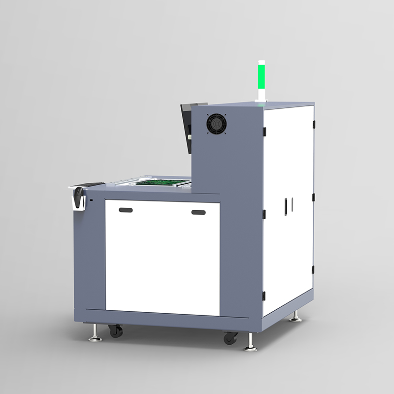
Core Evaluation Dimensions for Selective Soldering Equipment
Precision and Flux Application
A reliable solder joint starts with precise flux application. When evaluating selective soldering equipment, prioritize drop-jet fluxers over ultrasonic sprayers. Drop-jet mechanisms operate like inkjet printers, firing micro-droplets of flux exactly onto the target pin and pad. This precision prevents flux from spreading to un-soldered areas. Uncontrolled flux spread causes electromigration, dendritic growth, and severe board contamination, which act as critical failure modes in humid automotive environments.
Thermal Management and Preheating Capabilities
Overcoming the thermal mass of heavy copper boards requires a robust preheating architecture. Advanced selective systems utilize multi-zone preheating, combining bottom-side shortwave infrared (IR) heaters with top-side convection modules. This combination manages the thermal delta across the board, raising the internal temperature of the copper planes to around 110°C to 130°C before the mini-wave solder fountain makes contact. Proper preheating ensures the solder does not freeze upon contact with the through-hole, enabling rapid capillary action and complete hole fill without requiring excessive dwell time at the nozzle.
Throughput vs. Flexibility (System Architecture)
Equipment architecture must match your production volume. Standalone batch machines offer high flexibility and suit high-mix, low-volume production environments. They maintain quality while keeping the factory footprint and initial costs manageable. In-line modular systems fit high-volume automotive lines. These systems separate fluxing, preheating, and soldering into distinct modules connected by SMEMA conveyors, allowing multiple boards to process simultaneously. This modularity maximizes throughput and slashes cycle times for dedicated production runs.
Traceability and Data Logging
Automotive compliance audits and recall-prevention protocols demand rigorous traceability. Modern selective soldering systems feature closed-loop process control, monitoring parameters like solder temperature, wave height, flux volume, and nitrogen flow in real-time. Integrated barcode scanners link these process parameters to individual board serial numbers. Automated data logging ensures that if a field failure occurs, you can retrieve the exact soldering conditions for that specific unit, isolate the root cause, and limit the scope of potential recalls.
Assessing the Heavy Duty Soldering Machine Investment (Trade-offs)
Capital Expenditure vs. Operational Savings
Calculating the return on investment for a heavy duty soldering machine requires looking past the initial sticker price. The operational savings compound immediately. Selective soldering eliminates the need for expensive wave solder pallets, the labor-intensive application of masking tape, and the associated chemical cleaning processes. The dramatic reduction in thermal damage and solder bridging significantly lowers manual rework labor and scrap rates. These eliminated costs accelerate the break-even point, often justifying the capital expense within the first 12 to 18 months of operation.
Future-Proofing the Production Line
Investing in scalable selective soldering equipment aligns directly with future market trends. As vehicle architectures evolve toward 800V EV power management and complex ADAS sensor fusion, board densities will increase. A programmable selective system provides the agility to adapt to these next-generation requirements through simple software profile updates. You avoid constant physical equipment overhauls or the need to design new pallets for every board revision, ensuring long-term manufacturing viability.
Nitrogen Consumption Realities
Selective soldering relies on an inert nitrogen atmosphere at the solder nozzle. Nitrogen prevents the rapid oxidation of the molten solder, drastically reducing dross formation and improving the wetting characteristics of lead-free alloys like SAC305. You must evaluate your nitrogen supply strategy. Compare the logistics and recurring costs of bottled liquid nitrogen dewars against the upfront investment of an on-site nitrogen generation system. Automotive applications typically require high purity levels, keeping oxygen content below 50 parts per million (ppm) at the nozzle.
Consumables and Tooling
While masking costs disappear, selective soldering introduces specific consumables. You must account for the ongoing costs of solder alloys and fluxes optimized for localized application. The solder nozzles themselves wear out. Continuous exposure to molten lead-free alloys and aggressive fluxes degrades the nozzle plating over time, altering the wave dynamics. You must evaluate the lifespan and replacement costs of these nozzles as a standard component of your operational budget.
Implementation Risks and Mitigation Strategies
Programming and Operator Training
Transitioning to selective soldering introduces a steep learning curve. The process relies heavily on offline programming software, where engineers import Gerber or ODB++ data to define routing paths, flux volumes, and thermal profiles. Operators must understand complex thermal dynamics rather than just pushing buttons on a machine. Mitigate this risk by investing in comprehensive training programs. Utilize equipment with intuitive, visual programming interfaces that simplify the creation and adjustment of soldering recipes.
Maintenance and Nozzle Wear
Preventative maintenance dictates joint quality. The aggressive nature of modern fluxes and the high tin content of lead-free alloys rapidly degrade solder nozzles, leading to bridging or insufficient hole fill. Enforce strict, documented cleaning schedules.
Daily: De-dross the solder pot, check nitrogen flow, and tin the nozzles to prevent oxidation.
Weekly: Clean the drop-jet fluxer heads in an ultrasonic bath to prevent clogging.
Monthly: Inspect and vacuum the IR preheater zones to remove accumulated flux residue that could pose a fire risk.
Vetting Your Electronics Manufacturing Supplier
The success of a selective soldering implementation depends heavily on your equipment vendor. When vetting an electronics manufacturing supplier, prioritize their service level agreement (SLA) and the local availability of spare parts. Evaluate their applications engineering support. A competent supplier will conduct pre-purchase time-studies and run sample boards using your actual design files in their application lab. This validation proves their equipment can handle your specific thermal mass and cycle time requirements before you sign the purchase order.
Conclusion
For modern, high-reliability automotive electronics soldering, selective soldering is a baseline requirement for mixed-technology boards. The extreme thermal mass of EV power electronics and the high-density layouts of ADAS control units render traditional full-wave and manual methods obsolete. By isolating heat application and automating the flux and solder processes, manufacturers achieve the zero-defect quality and traceability demanded by the automotive sector. Aligning the machine architecture with your specific production realities ensures a smooth integration and a rapid return on investment.
Take the following actionable steps to advance your production capabilities:
Request a comprehensive board evaluation from shortlisted vendors to identify thermal bottlenecks in your current designs.
Demand a detailed cycle-time analysis based on your highest-volume assemblies to determine if a batch or inline system fits best.
Require a physical sample run using your actual board files to validate hole fill, wetting, and thermal profiles.
Audit your facility's current nitrogen supply infrastructure to determine if an on-site generation upgrade is necessary.
FAQ
Q: What is the difference between wave and selective soldering in automotive applications?
A: Wave soldering exposes the entire bottom of the board to molten solder, requiring expensive masking to protect sensitive components. Selective soldering uses a programmable, localized mini-wave to solder individual through-hole pins. This targets heat only where needed, completely eliminating the need for masking and protecting adjacent surface-mount devices from thermal damage.
Q: Does selective soldering equipment meet IPC Class 3 standards?
A: Yes. Selective soldering systems provide the automated repeatability and precise programmable parameters required to consistently achieve the strict hole-fill, wetting, and joint integrity specifications mandated by IPC-A-610 Class 3 and automotive IATF 16949 standards.
Q: How does selective soldering protect sensitive automotive components?
A: It protects components through extreme precision. The system uses a drop-jet fluxer and a highly controlled mini-wave nozzle to apply flux and solder only to specific pins. This establishes a strict thermal keep-out zone, preventing heat from transferring to adjacent, sensitive micro-components.
Q: Can a heavy duty soldering machine handle heavy copper boards used in EVs?
A: Yes, provided it is equipped with robust preheating architecture. Heavy copper acts as a heat sink. Advanced machines utilize multi-zone bottom IR and top convection preheating to raise the board's internal temperature, allowing the mini-wave to achieve proper capillary action without freezing.
Q: What is the typical ROI timeline for transitioning to selective soldering?
A: ROI timelines vary but are often accelerated by operational savings. The immediate elimination of custom wave pallets, masking tape, and manual rework labor, combined with increased yields and reduced scrap rates, typically offsets the initial capital expenditure within 12 to 18 months.
Q: What are the main maintenance requirements for selective soldering systems?
A: Critical maintenance includes strict nozzle care, as aggressive fluxes and lead-free alloys cause wear. Daily tasks involve de-drossing the solder pot and cleaning/tinning nozzles. Weekly maintenance requires calibrating the drop-jet fluxer and cleaning preheater zones to prevent flux residue accumulation.
Q: Why is nitrogen required for selective soldering?
A: Nitrogen creates an inert environment around the solder nozzle, preventing the rapid oxidation of molten solder. This drastically reduces dross formation, lowers maintenance requirements, and significantly improves the wetting characteristics of lead-free alloys, ensuring high-reliability joints.


