

- HomeProducts
-

What Is the Difference Between Single-Pot and Dual-Pot Selective Soldering?
Views: 0 Author: Site Editor Publish Time: 2026-11-09 Origin: Site


The increasing density of mixed-technology printed circuit boards (PCBs) makes through-hole soldering a primary bottleneck in modern electronic manufacturing. As surface mount technology shrinks, the remaining through-hole components—like heavy-duty connectors, relays, and power modules—require precise, repeatable soldering that manual labor simply cannot sustain. Production engineers must eliminate these manual soldering bottlenecks, ensure thermal consistency, and improve joint reliability without over-capitalizing on equipment that exceeds their throughput or flexibility requirements. Deciding on single pot vs dual pot selective soldering dictates the facility's cycle times, footprint efficiency, thermal management, and ability to handle multiple alloys. Choosing incorrectly leads to either idle machine time or a choked production line. We will break down the technical and operational differences between these systems to support an evidence-based equipment selection for your manufacturing floor.
Throughput vs. Flexibility: Single pot systems are ideal for high-mix, low-volume (HMLV) environments, whereas dual pot systems drastically reduce cycle times for high-volume production or complex boards requiring multiple nozzle sizes.
Alloy Management: Dual pot configurations eliminate the downtime and cross-contamination risks associated with swapping pots when running both leaded and RoHS-compliant (lead-free) assemblies.
Thermal Consistency: Faster cycle times in dual pot systems prevent the PCB from cooling down during the soldering process, maintaining optimal flux activation and reducing the risk of board warpage.
Scalability: Upgrading from a standalone single pot to a dual pot or multi-station inline system requires evaluating floor space, nitrogen consumption, and programming complexity.
Understanding the Core Mechanics
Single Pot Selective Soldering Machine Architecture
A standard single pot system features one solder reservoir constructed from titanium or specialized cast iron to withstand the corrosive nature of lead-free alloys. This reservoir houses a single electromagnetic or mechanical pump, an impeller, and a dedicated nozzle. A nitrogen shroud surrounds the nozzle, directing a laminar flow of inert gas over the liquid solder to displace oxygen and prevent dross formation. During operation, the PCB remains stationary while the pot moves via a robotic XYZ gantry. In some compact machine designs, the board moves over a stationary pot, though this limits the maximum board size the machine can handle.
These systems provide a straightforward, reliable method for automating through-hole soldering. They excel in contract manufacturing environments dealing with frequent changeovers, simpler board geometries, and single-alloy requirements. They offer a highly controlled process that eliminates the inconsistencies of manual hand soldering, ensuring repeatable capillary action within the plated through-holes.
However, single pot architectures carry inherent limitations based on their sequential nature. The operational sequence follows a strict linear path:
The drop-jet fluxer applies flux to the specific through-hole coordinates.
The bottom-side infrared (IR) heaters raise the board temperature to activate the flux and prevent thermal shock.
The XYZ gantry positions the solder nozzle under the first coordinate.
The pump increases RPM to raise the solder wave to the programmed height.
The gantry moves the nozzle along the programmed drag-soldering path or performs a stationary dip.
The pump decreases RPM, the wave drops, and the gantry moves to the next coordinate.
Because the machine must visit each pin one by one, the cycle time scales linearly with the number of through-hole components. If a board has 200 pins, the machine executes 200 individual movements. Prolonged cycle times lead to uneven thermal stress on the PCB. The first soldered joint cools significantly by the time the final joint is processed, potentially causing the FR4 substrate to warp or the flux to burn off before the final pins are soldered.
Dual Pot Selective Soldering Machine Architecture
Dual pot systems integrate two distinct solder reservoirs into a single machine footprint. These reservoirs either share a heavy-duty gantry or utilize completely independent robotic axes. This design fundamentally changes how boards are processed, shifting the operation from purely sequential to parallel.
The kinematics and control rely heavily on two independent solder pots XYZ motion. Independent robotic axes allow simultaneous soldering on different areas of the same board. Alternatively, the machine can execute parallel processing of two separate boards without collision. Advanced collision-avoidance algorithms constantly monitor the position of both gantries, ensuring they never intersect while optimizing the travel paths to minimize idle movement. This dual-mode functionality operates in two primary ways:
Mode 1 (Speed/Parallel Processing): Two pots filled with the exact same alloy work simultaneously on the same board or on a multi-up panel. If a board requires 200 solder points, Pot A handles the left hemisphere (100 points) while Pot B handles the right hemisphere (100 points). This effectively halves the cycle time.
Mode 2 (Flexibility/Multi-Tool Processing): Two pots run different alloys, such as SnPb (tin-lead) and SAC305 (lead-free). They can also run different nozzle sizes. Pot A might utilize a 12mm wetted nozzle for heavy connectors, while Pot B utilizes a 3mm micro-nozzle for tight clearances near surface-mount devices (SMDs).
Equipment Modularity and Retrofitting
Future-proofing the production line requires evaluating modular chassis designs. Production managers must determine if a single pot selective soldering machine can be retrofitted with a second pot as production scales. Not all entry-level frames can handle the added weight and kinematics of a second reservoir. A fully loaded solder pot can weigh over 50 pounds, and adding a second moving mass requires a highly rigid frame to prevent vibration from affecting wave stability.
Assessing infrastructure requirements is critical before attempting a field upgrade. You must verify if the existing machine frame, software licenses, and facility nitrogen supply can support the transition to a dual pot system. Upgrading often requires enhanced exhaust routing to handle the additional flux fumes and upgraded power drops to accommodate the second set of high-wattage heating elements.
Production Volume and Throughput Analysis
Cycle Time Reduction in High-Volume Environments
Establishing success criteria is the first step in optimizing high throughput PCB selective soldering. You need to define target cycle times, boards per hour (BPH), and takt time alignment. Cycle time calculations heavily favor dual pot systems in high-volume scenarios. Contrast the sequential point-to-point time of a single pot against the parallel processing capabilities of a dual pot system.
Panelized board optimization showcases the true power of dual reservoirs. Dual pots can solder two identical circuits on a multi-up panel simultaneously. This effectively doubles throughput per machine cycle without increasing the conveyor speed. Furthermore, thermal profile maintenance improves drastically. Faster cycle times prevent the PCB from cooling down during soldering. This ensures optimal flux activation and reduces thermal shock compared to prolonged single-pot cycles.
Operational Metric
Single Pot Architecture
Dual Pot Architecture
Cycle Time Scaling
Linear (scales directly per pin)
Up to 50% reduction via parallel processing
Alloy Changeover Time
Requires physical pot swap (1-2 hours)
Instant software-driven switching (0 minutes)
Nozzle Flexibility
One size per production run
Two distinct sizes available simultaneously
Thermal Stress on PCB
Higher risk on large, complex boards
Lower risk due to accelerated processing
Nitrogen Consumption
Baseline flow rate
Increased flow, mitigated by standby modes
Scaling to an Inline Selective Wave Soldering Production Line
Evaluating the transition from standalone batch processing to fully automated inline manufacturing requires a close look at material handling. Batch machines require operators to manually load and unload pallets, which introduces human error and slows down the overall takt time. Inline systems automate this transfer, moving boards seamlessly from the upstream surface-mount technology (SMT) line directly into the selective soldering process.
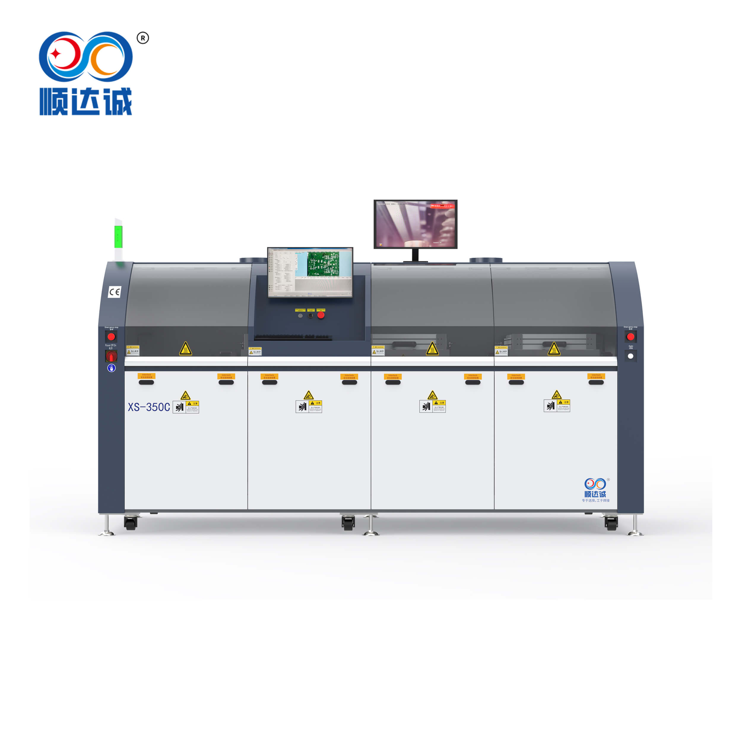
System integration determines the success of an inline selective wave soldering production line. Both single and dual pot systems must seamlessly integrate with SMEMA-compatible conveyors. These conveyors use pin chains or edge belts to transport the PCB without interfering with bottom-side components. The inline system typically separates the process into distinct zones: a drop-jet fluxing zone, a top/bottom IR pre-heating zone, and the soldering zone. Footprint efficiency plays a major role here. A dual pot inline system utilizes floor space much more efficiently than running two separate single pot machines side-by-side. It consolidates the fluxing and preheating zones, saving valuable factory real estate while doubling the soldering capacity.
Alloy Flexibility and Mixed Production
Managing Lead-Free and Leaded Requirements
The compliance challenge remains a massive hurdle for aerospace, medical, and military applications. These industries enforce strict isolation requirements for RoHS (lead-free) and non-RoHS (leaded) production. Mixing leaded and lead-free solder compromises joint integrity, alters the melting point of the alloy, and violates strict regulatory standards. Even trace amounts of cross-contamination can lead to field failures in mission-critical hardware.
The single pot workaround is notoriously inefficient. Operators face significant labor, downtime, and thermal stabilization time when physically swapping heavy solder pots. The process involves powering down the machine, waiting for the pot to cool slightly for safe handling, physically disconnecting the power and nitrogen lines, lifting the heavy pot out of the chassis, inserting the new pot, and waiting for the new alloy to reach its operating temperature (typically around 260°C to 300°C). Recalibrating wave heights after a swap often takes one to two hours, destroying production schedules. A dual pot selective soldering machine provides a distinct advantage here. It enables instant, software-driven switching between leaded and lead-free pots. This results in zero physical changeover time and zero cross-contamination risk, as each alloy remains completely isolated in its own reservoir, pump, and nozzle assembly.
Nozzle Size Variations for Complex Geometries
High-density board challenges force engineers to rethink their soldering strategies. Soldering large thermal mass components—such as power relays, thick ground planes, or heavy-duty connectors—requires large, high-flow nozzles to transfer adequate heat. If the nozzle is too small, the solder will freeze before it can wick up the through-hole barrel, resulting in a cold joint or insufficient barrel fill. Conversely, densely packed components require micro-nozzles to avoid damaging adjacent surface-mount devices (SMDs) or melting nearby plastic connectors.
Dual pots offer tool-free optimization. You can dedicate Pot A to a large wetted nozzle for heavy ground planes and Pot B to a fine-point nozzle for tight pitches. The machine automatically toggles between the two based on the soldering program. The software directs the large nozzle to solder the power components first, then retracts it and brings in the micro-nozzle to solder the delicate pin headers. This optimizes thermal transfer and prevents solder bridging without requiring physical tool changes mid-run.
Advanced Configurations: Expanding Beyond Dual Pot
The Role of Four Station Inline Selective Soldering
When extreme volume demands exceed standard dual pot capabilities, facilities must look toward modular, multi-station approaches. Defining the architecture of four station inline selective soldering reveals a highly optimized pipeline. This high-volume configuration consists of dedicated, physically separated zones: a fluxing station, a pre-heating station, soldering station 1, and soldering station 2. Often, these soldering stations utilize multiple pots themselves, creating a massive parallel processing environment.
Extreme scalability is achieved through line balancing and advanced software control. Routing software distributes soldering tasks across multiple stations to ensure no single station bottlenecks the conveyor. In a four-station setup, four different boards are processed simultaneously. While Board D is being fluxed, Board C is pre-heating, Board B is receiving its first set of solder joints at Station 1, and Board A is receiving its final solder joints at Station 2. If one board has a heavy concentration of through-hole components on the leading edge, Station 1 handles that section while Station 2 handles the trailing edge. This pipeline approach maximizes efficiency, allowing a completed board to exit the machine every few seconds rather than every few minutes.
Implementation Risks and Operational Realities
Maintenance, Dross Management, and Nitrogen Consumption
Implementation realities dictate that two pots mean twice the moving parts. You must maintain twice the pumps, twice the impellers, and twice the heating elements. Preventative maintenance schedules must reflect this increased hardware density to prevent unexpected downtime. Operators must clean the impellers regularly to prevent flux residue and oxidized solder from binding the pump shaft. The nitrogen shrouds also require frequent cleaning to ensure the laminar flow of gas remains unobstructed.
Consumable usage scales with the hardware. You must account for the nitrogen (N2) flow requirements to maintain an inert atmosphere over two pots instead of one. Advanced systems use software-controlled standby modes to conserve gas when a pot is idle, dropping the flow rate to a minimum baseline until the pot is called into action. Dross generation presents another operational reality. Dross is the oxidized solder that forms on the surface of the molten alloy. De-drossing dual reservoirs requires more labor and strict material handling to manage solder reclamation effectively, especially if two different alloys are in use. Operators must use dedicated dross tools for the leaded pot and the lead-free pot to prevent cross-contamination.
Process Control and Calibration
Wave stability becomes more complex with dual reservoirs. Monitoring and calibrating Z-axis height and wave stability for two independent nozzles requires precise maintenance protocols. The pump RPM must be tightly controlled to ensure the solder wave height remains consistent. If one wave fluctuates while the other remains stable, joint quality will vary across the same PCB, leading to unpredictable barrel fill and potential rework.
Fiducial recognition systems must work harder in dual pot environments. Vision systems must compensate for board stretch or warpage across two different soldering zones simultaneously. When a PCB is subjected to top and bottom IR pre-heating, the FR4 material expands slightly. Accurate fiducial alignment ensures that both nozzles hit their exact coordinates, recalculating the X and Y offsets in real-time to match the expanded board dimensions.
Programming Complexity and Operator Training
Software requirements scale with hardware capability. Programming collision-avoidance and path optimization for independent XYZ gantries introduces new complexities. Operators must understand how to route paths without causing mechanical interference between the two heavy solder pots. Poor programming can lead to inefficient travel paths, negating the speed advantages of the dual pot system.
Mitigation strategies rely heavily on modern software. Utilizing offline programming software, Gerber data import, and digital twin simulation prevents physical crashes. These tools optimize routing and reduce machine downtime during New Product Introduction (NPI). Operators can simulate the entire soldering cycle on a desktop computer, visually confirming that the two pots will not collide and that the cycle time is fully optimized, before sending the program to the factory floor.
Conclusion
The choice between single pot and dual pot selective soldering hinges entirely on the facility's product mix, throughput targets, thermal management needs, and alloy diversity. Specify a single pot system for HMLV, single-alloy environments where maximum throughput is not the primary constraint. Specify a dual pot system for high-volume production, dual-alloy requirements, or complex boards requiring multiple nozzle geometries without tool changes.
Execute the following steps to finalize your equipment selection:
Conduct a time-study simulation using actual Gerber files to compare cycle times between single and dual pot configurations.
Audit your facility's nitrogen generation or bulk supply capacity to ensure it can support dual shrouds without pressure drops.
Map out your floor space to determine if an inline pipeline configuration fits within your current material handling layout.
Schedule a machine demonstration to observe dual-pot kinematics and collision-avoidance software in action on your most complex board assembly.
FAQ
Q: What is the main advantage of a dual pot selective soldering machine over a single pot?
A: The primary advantage is halved cycle times achieved via simultaneous soldering. Additionally, dual pot systems offer the ability to run two different alloys or utilize two different nozzle sizes without requiring physical changeovers or machine downtime.
Q: Can a single pot selective soldering machine handle both leaded and lead-free solder?
A: Yes, but it requires physically swapping the solder pot, pump, and nozzle. This process causes significant downtime, often taking hours for thermal stabilization, and requires strict contamination controls to prevent mixing the alloys.
Q: How does two independent solder pots XYZ motion work?
A: Each pot is mounted on its own robotic gantry. This allows them to move and solder different components on the board simultaneously without colliding. The movements are managed by advanced collision-avoidance and path-routing software.
Q: Does a dual pot system consume twice as much nitrogen?
A: While nitrogen consumption is higher, it is rarely a strict 2x multiplier. Advanced shroud designs and software-controlled standby modes mitigate the increase by reducing gas flow when a specific pot is not actively soldering.
Q: Can I upgrade a single pot machine to a dual pot machine later?
A: This depends entirely on the manufacturer and the chassis design. Some modular systems allow for field retrofits. However, rigid entry-level frames generally cannot support the added weight, secondary gantry, and nitrogen routing required for a second pot.
Q: When should a facility upgrade to four station inline selective soldering?
A: Four-station systems become necessary when takt times are extremely tight. This configuration allows fluxing, pre-heating, and multiple soldering stages to occur simultaneously on different boards moving through the conveyor queue.


