

- HomeProducts
-

How to Reduce PCB Soldering Defects with Better Soldering Equipment
Views: 0 Author: Site Editor Publish Time: 2026-09-04 Origin: Site


Inconsistent solder joints in high-density electronics create a compounding financial impact on production lines. Rework, scrap, and field failures quickly erode profit margins and disrupt delivery schedules. Board complexity increases daily across the industry. Mixed-technology designs, heavy copper planes, and extreme miniaturization demand absolute precision. Baseline wave soldering systems fail to maintain acceptable first-pass yield (FPY) rates under these demanding conditions. Legacy manual techniques simply cannot keep up with modern component density. Mitigating these issues requires a fundamental shift in manufacturing strategy. You must move away from operator-dependent corrections and manual touch-ups. Success relies entirely on equipment-driven process control. Upgrading to advanced soldering equipment changes the production dynamic entirely. Optimizing reflow profiling eliminates thermal inconsistencies across the board. Implementing automated selective processes drastically reduces human error, ensuring repeatable quality and reliable field performance.
Key Takeaways
Upgrading soldering equipment shifts defect management from reactive rework to proactive process control, directly improving first-pass yield and throughput.
The transition to a selective soldering process is critical for mixed-technology boards where traditional wave soldering causes thermal damage or bridging.
Evaluating a selective wave soldering machine requires analyzing closed-loop thermal control, flux deposition accuracy, and nitrogen inerting capabilities.
Upstream equipment upgrades, such as automated stencil workflows and multi-zone reflow ovens, are equally vital for preventing paste-related defects before they occur.
The Operational Cost of PCB Soldering Defects (Problem Framing)
Establish baseline metrics for a successful assembly process before making any hardware changes. You need strict IPC-A-610 Class 2 or 3 compliance depending on your specific industry sector. Class 3 requires a minimum of 75% barrel fill for through-hole components, a metric that older machines struggle to hit consistently on thick backplanes. Target FPY should consistently exceed industry baselines, pushing toward 98% or higher. Maximum allowable rework time must remain strictly capped to preserve line throughput. When these metrics slip, outdated machinery is usually the root cause. Relying on manual inspection and hand-soldering correction drains labor resources and introduces dangerous variability into the production cycle.
Mapping common defects directly to equipment failures reveals systemic process issues. You can trace almost every major defect back to a lack of machine control.
Bridging and Solder Shorts: These plague older production lines running fine-pitch components. Legacy machines suffer from imprecise wave dynamics and poor fluid control. Inadequate flux application leaves critical areas unprotected during the thermal cycle. Poor stencil alignment in older printers causes massive paste volume errors, leading directly to shorts between adjacent pads.
Cold Solder Joints and Poor Wetting: These defects destroy electrical reliability and mechanical strength. They stem directly from insufficient pre-heating stages that fail to activate the flux chemistry. Mismatched reflow oven temperature profiles play a major role here. Oxidized solder baths ruin the wetting process entirely, preventing the formation of a strong intermetallic layer between the copper pad and the component lead.
Tombstoning and Solder Balling: These ruin surface mount yields. Uneven thermal distribution drives these specific errors, causing one end of a passive component to wet and pull faster than the other. Incorrect solder paste volume acts as another primary factor. Outdated ovens cannot maintain the precise thermal deltas required to heat the board evenly across all zones.
Blowholes and Outgassing: These compromise through-hole integrity severely. Trapped moisture in the board causes violent outgassing during the rapid heating phase. This expands trapped gases inside the FR4 material, blowing holes through the molten solder as it cools. This highlights the absolute need for proper pre-baking units and controlled pre-heating to drive out moisture before the board hits the wave.
Pad Lifting and Thermal Damage: These represent catastrophic, often unrepairable failures. Excessive dwell times destroy copper adhesion to the FR4 substrate. Uncontrolled localized heat from poorly calibrated machines causes severe board delamination. Incorrect tip selection and excessive temperatures during manual rework also lead directly to lifted pads, rendering the board scrap.
The hidden costs of rework are staggering and often undercalculated by production managers. Labor hours add up rapidly on complex, high-density boards. Thermal stress degrades adjacent components during manual fixes, pushing them past their specified thermal limits. Every time you apply a soldering iron to a board, you increase the intermetallic thickness, which makes the joint more brittle. This creates latent field failures later in the product's lifecycle. Field failures ruin a manufacturer's reputation permanently and trigger expensive warranty claims.
Defect Type
Primary Equipment Failure
Process Impact
Bridging / Shorts
Imprecise wave dynamics, poor stencil alignment
Requires manual wicking, risks pad damage
Cold Joints
Insufficient pre-heat, oxidized solder bath
Weak mechanical bond, intermittent electrical failure
Tombstoning
Uneven convection heating, poor zone control
Requires manual component replacement
Blowholes
Lack of pre-baking, rapid thermal ramping
Compromised barrel fill, fails IPC Class 3
Lifted Pads
Excessive dwell time, uncontrolled localized heat
Catastrophic board failure, high scrap rate
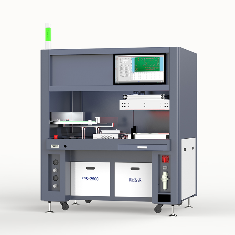
Solution Categories: Transitioning from Legacy to Advanced Soldering
Upgrading SMT stencil printers and reflow ovens forms the first line of defense against defects. Automated stencil workflows prevent volume-related defects entirely by ensuring consistent paste deposition. Integrating 3D Solder Paste Inspection (SPI) catches errors early, stopping bad boards before they enter the oven. Modern multi-zone reflow ovens match temperature profiles precisely. They adapt to specific solder paste specifications seamlessly, providing exact control over the soak and reflow zones. A modern 10-zone or 12-zone oven allows you to manipulate the time above liquidus (TAL) with extreme precision, ensuring heavy copper planes heat up without scorching low-mass components.
Traditional wave soldering carries severe limitations today. It lacks the necessary precision for modern high-density boards packed with sensitive components. Custom pallets are expensive to machine, clean, and maintain. They also take weeks to design and implement, delaying new product introductions. Full-board wave exposure creates a massive thermal shock risk. Double-sided assemblies suffer greatly under these legacy methods, often requiring secondary hand-soldering operations that bottleneck the entire floor.
Implementing a selective soldering process solves these exact challenges. It isolates specific through-hole components perfectly using miniature solder waves. This protects adjacent surface-mount devices from heat damage and flux contamination. It completely eliminates the need for expensive masking tapes and labor-intensive prep work. Custom pallets become obsolete overnight, streamlining the entire production floor. You can program the machine to adjust dwell times and wave heights for individual pins on the same board, providing unmatched process control.
Modern machinery integrates seamlessly with Automated Optical Inspection (AOI) systems. Inline AOI creates a powerful closed-loop feedback system. This allows for immediate defect detection on the line before the board moves to the next stage. Process correction happens in real-time. If the AOI detects insufficient hole fill, technicians can immediately adjust the pump RPM or pre-heat settings on the selective machine. Yield rates stabilize quickly when feedback loops are tight and data-driven.
Evaluation Dimensions: Matching Machine Features to Defect Reduction
Precision flux deposition systems dictate final joint quality. Drop-jet fluxers offer superior accuracy compared to older ultrasonic or foam fluxers. Drop-jet systems use piezoelectric valves to shoot micro-dots of flux exactly where needed, often reducing flux consumption by over 60%. Controlled flux volume prevents dangerous ionic contamination across the board surface, which is critical for no-clean processes. It also stops solder balling dead in its tracks by applying flux only to the barrel and pad. Accurate fluxing ensures proper hole-fill on thick boards by preparing the barrel for optimal capillary action.
Advanced pre-heating prevents thermal shock completely. Closed-loop IR or quartz pre-heaters maintain exact temperatures continuously, regardless of board mass. Top and bottom pre-heating zones prevent board warpage during the thermal cycle. Moisture-baking capabilities remove trapped humidity effectively before the solder phase. Programmable thermal profiles mitigate outgassing risks by ramping temperatures at the correct rate. They ensure proper capillary action for thick multi-layer boards heavily populated with copper planes.
Solder pot and wave dynamics define machine performance. You must evaluate these critically when selecting a selective wave soldering machine. Nitrogen-inerted environments are absolutely mandatory for modern lead-free alloys like SAC305. Nitrogen reduces dross formation significantly, saving money on wasted solder and reducing maintenance downtime. It improves wetting and prevents rapid oxidation of the molten wave. You want to look for systems that can maintain oxygen levels below 50 ppm at the wave. Nozzle design matters greatly for tight clearances between components. Wettable nozzles provide different flow characteristics than non-wettable variants, allowing for customized flow dynamics. Wave height stability ensures consistent through-hole penetration without causing adjacent bridging or skipped joints.
Material handling and cleanliness controls keep the process stable. Look for features minimizing handling-induced contamination, such as automated edge conveyors and SMEMA-compatible interfaces. Prevent oxidation prior to soldering at all costs by keeping boards in controlled environments. Ensure only pristine materials enter the solder wave. Cleanliness directly correlates to joint reliability and long-term performance in harsh environments.
Feature
Legacy Equipment
Advanced Equipment
Flux Application
Foam or broad spray, high waste, high contamination risk
Drop-jet, pinpoint accuracy, minimal residue
Thermal Control
Open-loop, inconsistent zones, prone to thermal shock
Closed-loop IR, precise profiling, smooth ramping
Atmosphere
Ambient air, high dross generation, poor wetting
Nitrogen inerted, low oxidation, superior capillary action
Tooling Requirements
Custom pallets required, expensive masking
Pallet-less, software controlled, zero masking
Programming
Manual adjustment, trial and error
Offline software, CAD import, exact recipe control
Trade-Offs and Total Value Influencing Factors
Capital expenditure must be weighed against yield improvements. Calculate your return on investment based on reduced rework labor strictly. Factor in lower flux and solder consumption accurately, as advanced machines waste very little material. Decreased scrap rates accelerate the payback period immensely. High initial costs offset long-term operational bleeds, making the investment highly justifiable for high-volume lines. You must also account for the elimination of wave pallet design and manufacturing costs.
Throughput versus flexibility remains a major consideration. Traditional wave soldering offers high volume output for simple, single-sided boards. A board passes over a traditional wave in seconds. However, a multi-nozzle selective approach provides extreme precision at the cost of cycle time. It offers unmatched flexibility for high-mix environments where board designs change frequently. You must align the machine type with your exact production mix to maximize utilization. If cycle time is a concern, look into dual-pot or multi-nozzle selective systems that can process multiple joints simultaneously.
Maintenance and consumables require dedicated ongoing budgets. Evaluate the specific costs of bulk nitrogen supply or on-site nitrogen membrane generators. Factor in regular nozzle replacement schedules, as these wear out over time due to the corrosive nature of lead-free solder. Dross management takes time and specific handling procedures, though nitrogen systems reduce this burden drastically. Machine calibration requires dedicated maintenance windows to ensure ongoing accuracy of the fluxer and wave height.
Operator dependency versus programming complexity is a critical trade-off. Advanced machines reduce manual soldering skill requirements drastically. You no longer need dozens of hand-soldering experts on the floor. However, they require highly skilled technicians. These technicians must program and optimize complex machine recipes using offline software to ensure perfect execution. Training your engineering staff on CAD import and recipe generation is mandatory for a successful rollout.
Implementation Risks and Mitigation Strategies for the PCB Assembly Manufacturer
Facility integration constraints require careful upfront planning. Address footprint requirements before signing purchase orders, ensuring adequate space for operation, maintenance access, and board loading. Plan for exhaust routing meticulously to handle flux fumes safely and maintain proper CFM draw. Nitrogen generation logistics demand serious attention, whether using bulk liquid tanks or on-site membrane generators. A reliable nitrogen supply with 99.99% purity is critical for continuous, uninterrupted operation.
Process validation and recipe development carry inherent risks. Poorly optimized machine parameters lead to temporary defect spikes during initial rollout. Mismatched reflow profiles cause immediate quality drops across the board. Mitigate these risks by utilizing dedicated thermal profiling boards equipped with K-type thermocouples. Attach these thermocouples directly to the most massive components and the thinnest areas of the board. Conduct extensive pilot runs before attempting full production. Leverage vendor training heavily for accurate recipe creation and troubleshooting.
Ensuring IPC compliance is absolutely non-negotiable. Document and validate the new equipment thoroughly during the site acceptance test. It must consistently meet strict IPC-A-610 standards for your specific product class. Focus heavily on hole fill metrics. You should perform destructive testing and cross-sectioning on initial pilot boards to verify barrel fill visually under a microscope. Fillet formation must be perfect every time, demonstrating excellent wetting and structural integrity.
Vendor support dictates long-term operational success. Evaluate the equipment manufacturer's guaranteed response time for service calls. Check local spare parts availability rigorously to avoid extended downtime. Ensure they have a robust technical support infrastructure capable of remote diagnostics. Partnering with a reliable PCB assembly manufacturer requires dependable machinery backing to maintain production schedules. If a pump fails, you need a replacement on your floor within 24 hours.
Conclusion
Relying on manual rework to fix PCB soldering defects is an unsustainable strategy. Modern electronics manufacturing demands absolute precision and repeatability. Equipment upgrades across the entire soldering workflow represent a necessary evolution to stay competitive. The cost of poor quality far outweighs the investment in modern machinery.
Request a detailed time-study from your equipment vendor immediately to compare current cycle times against projected automated times.
Run a complex test board on a vendor’s machine to validate defect reduction and inspect the hole-fill quality firsthand.
Audit your current rework labor hours to establish a firm baseline for your ROI calculation.
Upgrade your automated stencil printing process before replacing downstream wave machines to eliminate paste-related variables first.
Train your process engineers on offline programming software to ensure a smooth transition during machine installation.
FAQ
Q: What are the most common PCB soldering defects caused by outdated equipment?
A: Outdated equipment frequently causes cold joints, bridging, and outgassing. Poor thermal control leads to insufficient hole-fill and weak connections. Imprecise fluxing mechanisms in older machines also contribute heavily to solder shorts and ionic contamination across the board.
Q: How does a selective soldering process reduce thermal damage to PCBs?
A: It applies localized heat only to specific through-hole components using miniature solder waves. This targeted approach prevents the entire board from undergoing severe thermal shock. It protects sensitive adjacent surface-mount devices from the excessive heat exposure typical of traditional full-board wave soldering.
Q: Why is optimizing the reflow profile critical for preventing soldering defects?
A: Matching the oven's temperature profile to specific solder paste specifications is mandatory. Proper profiling ensures correct flux activation and prevents poor wetting. It also stops tombstoning and overheating, guaranteeing strong, reliable mechanical and electrical connections across components of varying thermal mass.
Q: How does stencil workflow impact PCB soldering defects?
A: Automated stencil printers ensure the correct solder paste volume is deposited. They also guarantee precise alignment on the pads using fiducial recognition. This proactive control prevents bridges, solder balls, and weak joints long before the board ever reaches the reflow oven.
Q: Can better soldering equipment eliminate the need for PCB rework entirely?
A: While advanced equipment drastically reduces first-pass yield failures, occasional rework remains inevitable due to component variations or bare board defects. The primary goal is statistical process control. When manual rework is required, using proper soldering iron temperatures prevents secondary damage like pad lifting.
Q: What features should a PCB assembly manufacturer look for in new soldering equipment?
A: Key features include nitrogen inerting capabilities and drop-jet fluxing systems. Programmable pre-heating zones are essential for thermal management. Closed-loop thermal feedback ensures the machine automatically adjusts to maintain consistent, repeatable quality across high-volume production runs.
Q: How does nitrogen improve the selective soldering process?
A: Nitrogen creates an inert environment around the solder wave. This prevents solder oxidation and significantly reduces dross formation. It also improves the surface tension of the molten solder, resulting in better wetting and superior capillary action for through-hole components.


