

- HomeProducts
-

Selective Wave Soldering Machine Settings Buyers Should Understand
Views: 0 Author: Site Editor Publish Time: 2026-07-13 Origin: Site


Procuring selective soldering equipment based solely on hardware specifications while ignoring software and parameter control capabilities introduces severe financial and operational risks. High-mix, high-reliability PCB assembly requires exact thermal and fluid dynamics to ensure joint integrity. Machines equipped with rigid or opaque parameter controls inevitably lead to thermal shock, solder bridging, insufficient hole fill, and exorbitant rework costs on the factory floor. When operators cannot fine-tune the process, scrap rates multiply.
Evaluating a machine's capacity for precise, repeatable control over fluxing, preheating, and soldering dynamics represents the most critical phase of the procurement process. Buyers must look beyond basic cycle times and mechanical footprints. The true capability of the equipment lies in how operators can manipulate and monitor the thermal and fluid variables to meet strict quality standards across diverse board designs. Without granular control, achieving consistent Class 3 solder joints becomes impossible.
Machine ROI is dictated by the granularity and repeatability of its selective soldering parameters, not just cycle time.
Closed-loop feedback systems for preheating and wave height are non-negotiable for high-mass, multi-layer boards.
Advanced selective soldering programming software reduces changeover times and minimizes operator-induced defects.
Procuring a custom selective soldering machine requires balancing throughput requirements with the flexibility of process parameter settings.
The Impact of Selective Soldering Parameters on Production Yield
The success criteria for selective soldering are strictly defined by IPC-A-610 standards. Manufacturers must achieve 100% barrel fill, zero solder bridging, and zero thermal damage to adjacent surface-mount devices. Meeting these criteria requires absolute mastery over the machine's operational variables. Every joint presents a unique thermal challenge depending on the surrounding copper weight, ground planes, and component density. A heavy copper ground plane will wick heat away from the joint instantly, demanding a completely different thermal profile than a simple signal pin.
The parameter ecosystem functions as an interdependent network. Flux volume, preheat temperature, solder temperature, wave height, and drag speed cannot be adjusted in isolation without affecting the others. For example, increasing the drag speed to improve cycle time might require a higher solder temperature or adjusted flux volume to maintain proper wetting. Understanding how these selective soldering parameters interact is essential for maintaining high production yields. When one variable shifts, the entire process window moves.
Buyers must evaluate machines based on how easily these parameters can be isolated, adjusted, and monitored in real-time. Equipment that buries settings behind complex menus or lacks real-time sensor feedback forces operators to rely on guesswork. A robust machine provides clear, digital readouts and allows for granular adjustments to each variable, ensuring that the process remains stable across different production batches. You need to see exactly what the machine is doing at any given millisecond.
Insufficient Hole Fill: Often caused by inadequate preheat temperatures or insufficient dwell time, preventing the solder from flowing up the barrel.
Solder Bridging: Typically the result of excessive wave height, incorrect peel-off speed, or insufficient flux application.
Solder Balls: Frequently linked to excessive flux volume, rapid preheat ramp rates causing flux solvent boiling, or improper nitrogen inertion.
Thermal Damage: Caused by excessive dwell times or preheat temperatures exceeding the component's maximum thermal threshold.
Flux Deposition Settings: Precision vs. Overspray
Drop-Jet vs. Ultrasonic Fluxing Controls
Flux application dictates the success of the entire soldering process. Drop-jet fluxers require precise control over frequency, nozzle orifice size, valve open time, and fluid pressure. These settings allow the machine to deposit micro-dots of flux exactly where needed, penetrating the through-hole without flooding the surrounding area. Ultrasonic fluxers, conversely, atomize the flux and require careful adjustment of air pressure and spray width to prevent overspray onto adjacent components. Overspray can lead to reliability issues, especially with no-clean fluxes that remain active if not fully heated.
Fluxing Technology
Key Parameter Controls
Best Application
Maintenance Focus
Drop-Jet
Frequency, Open Time, Pressure, Orifice Size
High-precision, tight clearance areas, dense boards
Nozzle clogging, valve seal wear
Ultrasonic
Atomization Air, Spray Width, Flow Rate
High-speed, wider deposition zones, connectors
Atomizer horn cleaning, air filter replacement
Buyers must evaluate the machine's ability to handle different flux chemistries through setting adjustments. No-clean, water-soluble, and high-solid fluxes possess different viscosities, specific gravities, and evaporation rates. The equipment must offer programmable profiles to accommodate these chemical differences without clogging the nozzles or depositing excessive residue. A machine that cannot adjust its pump pressure to handle a high-rosin flux will fail on the production floor.
Volume, Velocity, and Flow Monitoring Calibration
Programmable flux drop size, stroke frequency, and step pitch are mandatory for achieving the correct flux volume. Insufficient flux leads to poor wetting and dry joints, while excessive flux causes sticky residues and potential electromigration failures in the field. Precise machine settings mitigate these risks by ensuring consistent deposition volume regardless of the board's travel speed. The fluxer must synchronize perfectly with the gantry movement.
Modern equipment must include real-time digital flow sensors and spray confirmation pressure settings. These sensors verify that flux is actually being applied, preventing dry-run cycles that ruin expensive assemblies. Evaluating this technical gap is necessary; machines lacking closed-loop flux monitoring rely on visual inspection, which is inadequate for high-reliability manufacturing. If the flux nozzle clogs halfway through a run, the machine must alarm and stop immediately.
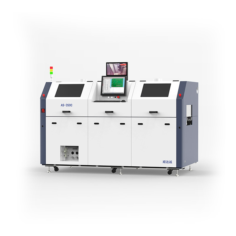
Preheating Controls and PCB Process Parameter Setting
Top vs. Bottom Heat Ramping Rates
Programmable thermal ramp rates prevent thermal shock to sensitive components like ceramic capacitors and avoid PCB delamination. Industry standards typically dictate a ramp rate of 1-2°C per second. The PCB process parameter setting interface must allow engineers to define these ramp rates precisely for both top and bottom heating modules. Pushing heat too fast boils the flux solvents violently, creating solder balls and voids.
Evaluating the settings for infrared (short or medium wave) versus forced convection preheaters is essential. Forced convection provides more uniform heating across varying component masses, while IR heating is faster but heavily influenced by component color and reflectivity. The software must accommodate the specific heating physics of the installed modules. Heavy copper boards often require a combination of bottom-side IR for rapid energy transfer and top-side convection for uniform soaking.
Closed-Loop Temperature Feedback
Buyers must demand pyrometer-driven, closed-loop control for the preheating stage. Static power settings are insufficient because they do not account for variations in ambient temperature, board mass, or tooling fixtures. Closed-loop systems continuously monitor the actual board surface temperature and adjust the heater output dynamically. This guarantees the board reaches the exact activation temperature required by the flux chemistry.
The machine should automatically modulate the heating elements based on these real-time readings. This ensures that every board enters the soldering module at the exact target temperature, eliminating the risk of cold solder joints caused by inadequate preheating. If a heavy pallet absorbs too much heat, the closed-loop system will extend the soak time automatically to compensate.
Zone-to-Zone Transition Time Parameters
The transit settings governing the speed at which the PCB moves from the preheat chamber to the solder module dictate thermal retention. If the transition is too slow, the board loses its top-side target temperature, compromising capillary action during soldering. The software must allow for rapid, programmable transfer speeds to minimize this thermal drop-off. Every second lost during transfer reduces the effectiveness of the preheat cycle.
Solder Pot and Pump Dynamics: Mastering the Wave
Solder Wave Height, Pump RPM, and Temperature Stability
Controlling the solder wave requires high-resolution settings for pump RPM and electromagnetic wave stability. The wave must remain perfectly flat and stable to ensure consistent contact with the through-hole pins. Fluctuations in wave height lead to skipped joints or massive solder bridges. Mechanical pumps require constant RPM adjustments as the impeller wears, whereas electromagnetic pumps offer more consistent flow over time.
Automatic wave height calibration settings using contact-finger or laser-sensor arrays compensate for pump wear and solder alloy density changes over time. Additionally, solder pot temperature tolerance settings must demand precision of at least ±2°C up to 300°C+. Proper selective wave soldering machine settings ensure the alloy remains in its optimal fluid state. A temperature drop of just a few degrees can drastically alter the surface tension and wetting characteristics of lead-free alloys.
Contact Time, Dwell, and Peel-Off Speed
The actual soldering event is governed by approach speed, dwell time, and drag or peel-off speed. Dwell time, typically ranging from 1 to 3 seconds, dictates how long the pin remains in the solder to achieve full barrel fill. Approach speed controls the initial thermal transfer, preventing solder splash as the nozzle contacts the board.
Programmable peel-off speeds and exit-angle dynamics prevent solder bridging on fine-pitch connector pins. By controlling exactly how fast the nozzle pulls away from the joint, the machine utilizes the surface tension of the molten solder to pull excess alloy back into the nozzle, leaving a perfect fillet. Different pin pitches require different peel-off speeds to break the solder web effectively.
Component Type
Recommended Dwell Time
Recommended Peel-Off Speed
Standard Through-Hole Resistor
1.0 - 1.5 seconds
3.0 - 5.0 mm/sec
Heavy Ground Pin Connector
2.5 - 3.5 seconds
1.5 - 2.5 mm/sec
Fine-Pitch Multi-Pin Header
1.5 - 2.0 seconds
1.0 - 1.5 mm/sec
Nitrogen Inertion and Oxygen PPM Settings
Nitrogen flow rates and purity levels heavily influence solder wetting and dross formation. Target settings should maintain oxygen levels below 20-50 PPM at the soldering site. The software must provide clear monitoring and adjustment parameters for the nitrogen shroud. High oxygen levels lead to rapid dross accumulation, which clogs nozzles and causes bridging.
Programmable N2 idle settings reduce gas consumption when the machine is waiting for the next board. By automatically dropping the flow rate during idle periods, manufacturers can significantly optimize consumable costs without compromising the inert environment during active soldering. The system should purge the shroud automatically just before the next board arrives.
Automated Nozzle Cleaning and Tinning Cycles
Settings for scheduling mechanical cleaning and automated nozzle re-tinning frequencies prevent de-wetting of the nozzle edge. Whether using rotating brushes, chemical sprays, or adipic acid activation, the machine must allow operators to program these maintenance cycles based on board count or operating time. Consistent nozzle tinning is mandatory for directional wave stability. A dry nozzle edge causes the solder wave to pull to one side, missing the target pins entirely.
Board Positioning, Fiducial Correction, and Warpage Compensation Parameters
Vision System Alignments and Camera Settings
The software must handle fiducial capture parameters, alignment tolerance windows, and auto-rejection offsets flawlessly. Vision systems ensure that the programmed soldering coordinates perfectly match the physical board position. If the board is slightly skewed in the conveyor, the camera settings calculate the offset and adjust the entire soldering path dynamically. This prevents the nozzle from crashing into adjacent SMD components.
Laser-Based Warpage and Z-Axis Dynamic Correction Settings
Large or thin PCBs warp during the preheating phase due to thermal expansion. Laser sensors map board flatness in real-time, feeding data back to the control software. The Z-axis profile settings then adjust dynamically to maintain a constant nozzle-to-board distance, ensuring consistent wave contact pressure across the entire warped assembly. Without dynamic Z-axis correction, the wave will flood low spots and completely miss high spots.
Mechanical Clamping and Pin-Support Parameters
Motorized PCB edge gripper settings and programmable pneumatic support pin heights handle heavy-mass multi-layer assemblies. Proper mechanical clamping prevents the board from shifting during the high-speed movements of the fluxer and solder pot, maintaining the integrity of the programmed coordinates. Heavy boards will sag in the middle without programmable center support pins, destroying the Z-axis calibration.
Selective Soldering Programming and Software Usability
Offline Programming vs. Inline Adjustments
The capability to generate recipes offline using Gerber, ODB++, or CAD data without halting production is a massive operational advantage. Advanced selective soldering programming software allows engineers to build and simulate the entire process on a separate PC. Visual programming interfaces are vastly superior to manual coordinate entry, reducing setup time and minimizing human error. You can verify nozzle clearances visually before the board ever hits the machine.
Path Optimization and Keep-Out Zone Algorithms
Advanced software automatically calculates the most efficient routing for the solder nozzle. It factors in clearance and keep-out zones around tall SMD components to prevent collisions. Path optimization algorithms reduce overall cycle time by minimizing unnecessary nozzle travel between soldering points. The software should automatically sequence the joints to manage heat input, preventing localized overheating on dense boards.
Traceability, CFX, and MES Integration
Aerospace, medical, and automotive sectors require strict compliance and traceability. The software must log all selective wave soldering machine settings per board via barcode scanning. Compatibility with modern communication standards, including IPC-2591 (CFX) and IPC-Hermes-9852, ensures seamless integration with factory Manufacturing Execution Systems (MES). Every flux drop, preheat temperature, and solder dwell time must be recorded and tied to the specific board serial number.
Specifying a Custom Selective Soldering Machine
Modular Upgrades vs. Fixed Configurations
Buyers face trade-offs between purchasing a standardized unit and a custom selective soldering machine tailored for specific board sizes or dual-alloy requirements. Custom configurations allow for dual-pot systems that handle both lead-free and tin-lead alloys in the same footprint, managed by sophisticated software parameters to prevent cross-contamination. Modular systems allow you to add a second preheat zone or a secondary fluxer as your production volume scales.
Balancing Throughput with Parameter Flexibility
There is a conceptual trade-off between multi-nozzle dip systems and single-nozzle point-to-point systems. Multi-nozzle systems offer high throughput but feature rigid settings, making them suitable for high-volume, low-mix production where every board is identical. Single-nozzle systems provide lower throughput but offer maximum parameter flexibility, ideal for high-mix environments requiring individual joint optimization. You must match the machine architecture to your specific production mix.
Implementation Risks and Mitigation Strategies
Operator Training and Parameter Lockouts
Unauthorized parameter changes on the factory floor pose a significant risk to production yield. Operators attempting to tweak settings without engineering approval often cause more defects than they solve. To mitigate this, evaluate machines with robust user-level access controls, multi-tier login credentials, and strict engineering lockouts. Only qualified process engineers should have the password to alter dwell times or pump RPMs.
Maintenance Impact on Setting Drift
Poor maintenance directly causes actual performance to drift away from programmed settings. Clogged flux nozzles, dross buildup in the solder pot, and pump axle wear alter fluid dynamics. Look for machines equipped with automated maintenance alerts, integrated dross management systems, and self-cleaning parameter cycles to maintain baseline performance. If the machine does not tell you when it needs maintenance, you will only find out when the boards start failing inspection.
Conclusion
Hardware alone cannot guarantee IPC-compliant solder joints; the software and control systems dictate the final yield. The true value of a selective soldering machine lies in the precision, repeatability, and traceability of its process settings.
Eliminate vendors who cannot demonstrate closed-loop preheating control and automatic warpage compensation during the evaluation phase.
Request a live demonstration using your most complex, high-mass PCB assembly to validate parameter flexibility and thermal capacity.
Verify that the machine software supports strict user-level access controls to prevent unauthorized setting modifications on the floor.
Audit the offline programming software to ensure it can import your specific CAD or Gerber files without requiring manual coordinate entry.
FAQ
Q: What are the most critical selective soldering parameters to monitor?
A: The most critical parameters include flux deposition volume, preheat thermal ramp rate, solder pot temperature, dwell time, and peel-off speed. These variables directly dictate hole fill quality and the prevention of solder bridging.
Q: How does selective soldering programming differ from wave soldering?
A: Selective programming focuses on point-to-point precision and individual joint parameter control using CAD or Gerber data. Wave soldering applies a continuous wave across the entire board with global settings, offering far less granular control.
Q: Why is closed-loop preheating necessary for PCB process parameter setting?
A: Closed-loop preheating uses pyrometers to read actual board surface temperatures, adjusting heater output dynamically. This compensates for varying thermal masses, preventing thermal shock and ensuring proper capillary action during soldering.
Q: Can a custom selective soldering machine handle multiple solder alloys?
A: Yes. Custom machines can be configured with dual solder pots and dual nozzles. The software manages the changeovers and specific temperature profiles for each alloy, preventing cross-contamination between lead-free and tin-lead processes.
Q: What is the ideal peel-off speed in selective soldering?
A: Ideal peel-off speeds typically range from 1 to 5 mm/sec depending on pin density and alloy. Slower peel-off speeds utilize surface tension to draw excess solder back into the nozzle, effectively preventing bridges on fine-pitch components.
Q: How do nitrogen settings affect selective wave soldering?
A: Nitrogen displaces oxygen at the soldering site. Proper N2 flow settings reduce oxygen levels below 50 PPM, which drastically minimizes dross formation, improves solder wetting, and ensures shiny, reliable solder joints.
Q: How does the machine compensate for PCB warpage during soldering?
A: Advanced machines use laser-mapping sensors to measure board warpage in real-time. The software dynamically adjusts the Z-axis height parameters during the run to maintain a perfectly consistent distance between the solder nozzle and the board surface.


