

- HomeProducts
-

Cold Solder Joints in Selective Soldering and How to Reduce Them
Views: 0 Author: Site Editor Publish Time: 2026-08-03 Origin: Site


Even minor thermal inconsistencies in automated soldering lead to high rework rates, scrapped assemblies, and compromised field performance. When dealing with high-mass components, thick multi-layer boards, or heavy copper planes, selective soldering processes are uniquely vulnerable to localized thermal deficits. These deficits prevent proper intermetallic bonding, resulting in defects that threaten product integrity. Resolving these defects requires a dual approach. First, precise thermal profiling and process control must be established on the factory floor. Second, manufacturing teams must evaluate whether their current hardware capabilities meet production demands. Identifying the root causes of cold solder joints in selective soldering is the first step toward optimizing yield and ensuring long-term assembly reliability. You cannot fix what you do not measure, and relying on operator guesswork will only compound the problem.
Thermal Management is the Primary Variable: Insufficient heat energy at the barrel and pad is the root cause of cold joints; optimizing top- and bottom-side preheating is non-negotiable.
Process Control vs. Hardware Limitations: Differentiate between defects caused by poor programming (dwell time, pump speed) and those caused by inadequate machine specifications.
Equipment Capabilities Dictate Yield: Modern selective wave soldering machines require closed-loop thermal monitoring and programmable fluxing to maintain consistent PCB solder joint reliability.
Supplier Expertise Matters: Selecting a selective soldering equipment supplier must be based on their ability to provide application-specific thermal profiling and ongoing process support.
The Mechanics and Impact of Cold Solder Joints in Selective Soldering
Defining the Defect (Visual, Metallurgical, and IPC Standards)
A cold solder joint typically exhibits a dull, grainy, or irregular surface finish. Visually, it lacks a proper meniscus, indicating incomplete wetting against the pad and the component lead. Metallurgically, the failure occurs because sufficient thermal energy was not present to form an adequate intermetallic compound (IMC) layer between the component lead and the PCB pad. An ideal IMC thickness ranges from 0.5 to 2.0 microns. Without this layer, you do not have a metallurgical bond; you merely have metal sitting on top of metal.
Industry standards, such as IPC-A-610, dictate specific vertical solder fill requirements for Class 2 and Class 3 assemblies. Cold solder joints fail to meet these criteria, as the solder does not flow completely through the barrel, leaving voids and weak mechanical connections. When inspecting these joints, operators often find that the solder froze before it could achieve capillary action up the plated through-hole.
IPC-A-610 Class
Vertical Fill Requirement
Acceptance Criteria for Wetting
Impact of Cold Solder Joints
Class 1 (General)
Not specified, but must show wetting
Evidence of good wetting on primary side
Often passes visual but fails under stress
Class 2 (Dedicated Service)
75% vertical fill minimum
270 degrees of circumferential wetting
Fails inspection due to incomplete barrel fill
Class 3 (High Performance)
75% vertical fill minimum (often pushed to 100% internally)
330 degrees of circumferential wetting
Immediate rejection; requires destructive testing
Impact on PCB Solder Joint Reliability
The long-term consequences of cold joints severely compromise PCB solder joint reliability. These weak connections are highly susceptible to mechanical shock and thermal cycling fatigue caused by mismatched coefficients of thermal expansion between the FR4 substrate, the copper barrel, and the component lead. Over time, this leads to intermittent electrical connectivity or complete failure in the field.
The business impact is substantial. Manufacturers face the high cost of manual rework, destructive testing requirements, and warranty claims resulting from field failures. Preventing these defects at the machine level is far more cost-effective than attempting to repair them post-production. Reworking a thick multi-layer board often requires massive heat input from a soldering iron, which risks lifting pads, delaminating the board, or damaging adjacent surface-mount components.
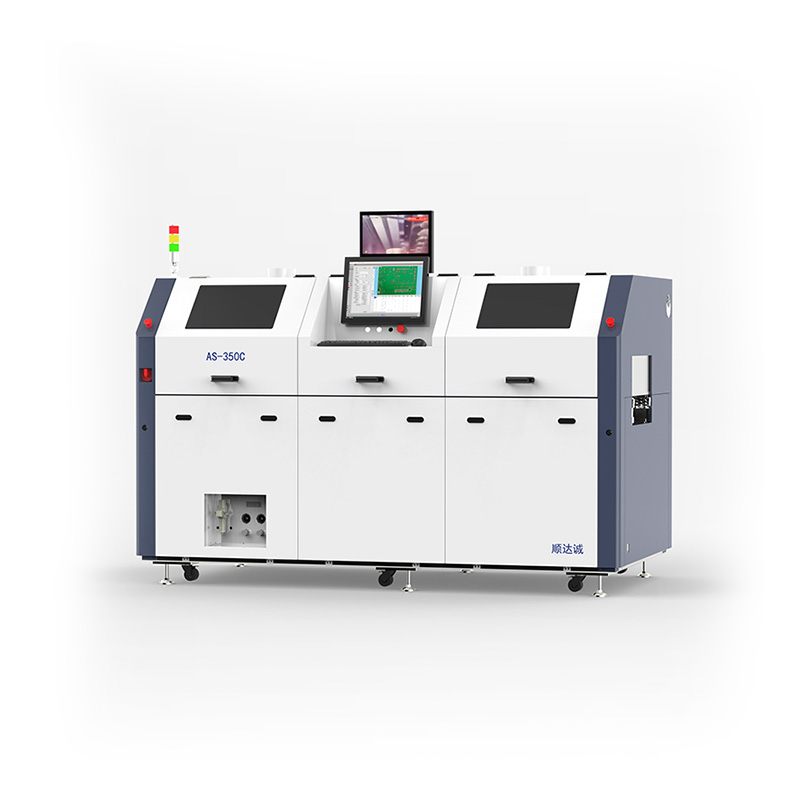
Root Causes of Thermal Inadequacy in the Soldering Process
High Thermal Mass, Lead-Free Alloys, and Copper Planes
Heavy copper layers act as internal heat sinks. They draw thermal energy away from the through-hole barrel faster than the solder wave can supply it. This rapid heat dissipation prevents the localized area from reaching the required soldering temperature. When you have a 2-ounce or 4-ounce copper ground plane connected directly to a through-hole without thermal reliefs, the wave struggles to overcome that thermal drain.
Furthermore, lead-free alloys, such as SAC305, require higher processing temperatures—typically around 260°C to 270°C—compared to traditional SnPb alloys. This increased thermal demand exacerbates the risk of cold joints, particularly on assemblies with high thermal mass. The liquidus temperature of SAC305 is roughly 217°C, meaning the board must be significantly preheated to prevent the wave from freezing upon contact.
Flux Starvation and Thermal Degradation
Proper flux activation is critical for oxide reduction and wetting. Insufficient preheating fails to activate the flux chemistry, while over-preheating can prematurely burn off the active ingredients. Without active flux, the solder cannot wet the pad or the component lead, leading to poor joint formation.
We often see operators increase the preheat temperature to solve a hole-fill issue, only to create a flux starvation issue. The flux carrier evaporates too quickly, leaving a dry, oxidized pad by the time the board reaches the solder nozzle. This requires a delicate balance of time and temperature.
Verify the flux manufacturer's recommended activation temperature profile.
Measure the top-side board temperature to ensure it does not exceed the flux's degradation point.
Check the drop-jet fluxer for clogs or inconsistent spray patterns that might leave areas unfluxed.
Ensure the time between flux application and wave contact does not exceed the flux's active lifespan.
Improper Dwell Time and Wave Dynamics
There is a constant trade-off between throughput speed and thermal transfer. Incorrect solder pump RPM, unstable wave height, or an improper nozzle distance reduces the contact time necessary for capillary action to draw the solder up the barrel. If the wave is too low, it barely kisses the bottom of the board, transferring almost no heat.
If the dwell time is too short, the joint will not reach the required temperature, resulting in incomplete fill and a cold joint. Conversely, if the dwell time is too long, you risk dissolving the copper pad entirely into the solder pot, a phenomenon known as copper dissolution, which is highly prevalent with lead-free alloys.
Nozzle Oxidation and Dross Accumulation
Dross buildup on the nozzle de-wets the nozzle tip, causing asymmetric wave flow. This disruption leads to temperature drops at the wave boundary. Consequently, the solder wave fails to deliver consistent thermal energy to the joint, causing localized cold soldering defects. A clean, fully wetted nozzle is mandatory for a stable, predictable wave.
Process Control Strategies to Prevent Cold Solder Joints
Optimizing Preheating Selective Soldering
Preheating plays a critical role in reducing thermal shock and bridging the temperature gap before the board meets the solder wave. Proper preheating selective soldering ensures that the assembly requires less thermal energy from the wave itself. You want the board to do the heavy lifting thermally, not the solder nozzle.
For thick, multi-layer boards, combining top-side infrared (IR) quartz preheating with bottom-side forced convection provides balanced thermal distribution. Target top-side board preheat temperatures typically range from 100°C to 120°C for lead-free applications to ensure successful vertical hole fill. Bottom-side convection helps push heat up through the vias, preparing the barrels for the incoming solder.
Preheat Technology
Mechanism
Best Application
Limitations
Infrared (IR) Quartz
Radiant heat transfer
Top-side heating, rapid temperature ramps
Color-sensitive; dark components absorb more heat than light ones
Forced Convection
Heated air circulation
Bottom-side heating, heavy copper boards
Slower ramp rates; requires more physical space in the machine
Closed-Loop Hybrid
Combines IR and Convection with pyrometer feedback
Complex, high-mass assemblies requiring strict tolerances
Higher initial equipment cost
Profiling and Solder Pot Temperature Management
Establishing a baseline thermal profile using embedded thermocouples on high-mass components is essential. Profiling tools help verify that the board reaches the necessary temperatures without exceeding component limits. You must place thermocouples on the heaviest ground planes and the lightest components to understand the thermal delta across the assembly.
Simply increasing the solder pot temperature to compensate for cold joints is dangerous. It increases the risks of copper dissolution, component damage, board delamination, and accelerated dross generation. Instead, operators should focus on optimizing dwell time and preheat profiles. Pushing a solder pot to 300°C will destroy your boards and rapidly degrade your pump impellers.
Nitrogen (N2) Inerting and Wave Stability
Nitrogen inerting at the nozzle prevents oxidation of the solder wave. Maintaining nitrogen purity with a target of less than 20-50 ppm of oxygen lowers the surface tension of the solder. This improves wetting dynamics and capillary action, significantly reducing the likelihood of cold joints. A proper nitrogen shroud keeps the wave clean and allows the solder to flow freely into the microscopic crevices of the plated through-hole.
Evaluating a Selective Wave Soldering Machine for Thermal Stability
Closed-Loop Temperature Monitoring and Control
Real-time pyrometers and closed-loop feedback systems are necessary to ensure the board reaches the exact target temperature before the wave initiates. This control prevents boards from being soldered while too cold, a primary cause of defects. If a board enters the machine cold due to a factory ambient temperature drop, the closed-loop system will hold it in the preheat zone until it hits the programmed setpoint.
Programmable Flux Deposition and Verification
Precise, localized flux application using accurate drop-jet fluxers prevents thermal drain caused by over-fluxing while ensuring adequate oxide removal. Automatic flux volume verification systems help maintain process consistency across production runs. If the fluxer misfires, the system should flag the board immediately rather than allowing it to proceed to the solder wave and fail.
Solder Level and Wave Height Calibration
Automated solder wire feeders maintain consistent pot volume and thermal capacity. Automatic wave height correction systems compensate for pump wear and nozzle dynamics, ensuring precise dwell times and consistent thermal transfer. As the pump impeller wears down over thousands of hours, the wave height will naturally drop unless the machine automatically adjusts the pump RPM to compensate.
Nozzle Design and Multi-Wave Capabilities
Single-nozzle systems offer high flexibility but lower throughput, while multi-nozzle dip systems provide high throughput but require complex tooling. The choice depends on the specific assembly requirements and the system's ability to maintain thermal stability across diverse board layouts. A high-quality selective wave soldering machine will allow for rapid nozzle changes without requiring extensive recalibration.
Choosing the Right Selective Soldering Equipment Supplier
Assessing Technical Support and Application-Specific Process Profiling
Evaluating a vendor's application engineering team is crucial. A reliable selective soldering equipment supplier should be willing to run specific high-mass, multi-layer boards in their application lab and provide detailed cross-sectional data to prove their machine's capabilities. Do not buy a machine based on a brochure; demand a physical trial using your most difficult assembly.
Machine Calibration Standards and Repeatability
Gauge Repeatability and Reproducibility (GR&R) data and machine-to-machine consistency are important indicators of equipment quality. Suppliers must demonstrate that their machines can repeatedly produce reliable joints under production conditions. If you program a profile on Machine A, it should run identically on Machine B without requiring manual offsets.
Long-Term ROI and Yield Calculations
Calculating ROI should factor in reduced manual touch-up, lower scrap rates, reduced dross generation, and increased throughput compared to manual soldering or legacy machines. High-quality equipment justifies its cost through improved yield and reliability. When you eliminate the need for three manual soldering operators and reduce your scrap rate to near zero, the machine pays for itself rapidly.
Conclusion
Eliminating cold solder joints requires moving beyond trial-and-error operator adjustments to a data-driven approach centered on precise preheating, closed-loop thermal profiling, and stable wave dynamics. Engineering teams should audit their current preheating capabilities and wave stability before deciding whether to optimize their current equipment or partner with a new supplier. Stop guessing with pot temperatures and start measuring your thermal profiles.
Conduct a comprehensive thermal profile audit on your highest-failure assemblies using embedded thermocouples.
Measure the thermal delta across the board to identify specific cold spots and adjust your preheat zones accordingly.
Inspect your current nozzles for dross buildup and verify your nitrogen purity levels at the wave boundary.
Request a proof-of-concept demonstration using your highest-mass PCB from a qualified equipment supplier to verify process improvements.
FAQ
Q: What is the most common cause of cold solder joints in selective soldering?
A: The most common cause is insufficient thermal energy at the joint. This happens due to inadequate preheating, the higher thermal demands of lead-free alloys, or high-mass copper planes acting as internal heat sinks that pull heat away from the barrel.
Q: How does preheating selective soldering prevent defects?
A: Preheating activates the flux, prevents thermal shock, and raises the board temperature closer to the liquidus point of the solder alloy. This minimizes the thermal load required from the solder wave itself, ensuring proper joint formation and complete barrel fill.
Q: Can increasing the solder pot temperature fix cold solder joints?
A: Increasing pot temperature is risky and not recommended. It causes component damage, pad lifting, and accelerated copper dissolution. Optimizing preheating and increasing contact time are safer and more effective solutions for achieving proper thermal transfer.
Q: How do you inspect a PCB for cold solder joints?
A: Inspection involves visual checks for dull or grainy finishes per IPC-A-610 standards. X-ray inspection verifies vertical barrel fill, and metallurgical cross-sectioning confirms the thickness of the intermetallic compound layer between the lead and the pad.
Q: What features should I look for in a selective wave soldering machine to improve reliability?
A: Look for closed-loop preheat control, nitrogen inerting, precise drop-jet fluxing, automatic wave height calibration, and stable solder pump dynamics to ensure consistent thermal transfer and repeatable production yields.
Q: Why is nitrogen used in selective soldering?
A: Nitrogen displaces oxygen at the wave, preventing dross formation. It also lowers the solder's surface tension, which significantly improves hole-fill, wetting, and capillary action, allowing the solder to flow easily into tight spaces.


